
HR 352 Freyja
Update Jan 2025 - Freyja is now sold. This website will subsequently be closed once I figure out how to do it!
Why an HR352 and an account of all the works completed which I hope will be useful to others.
Note: Configured for optimum use on desktop or laptop

WHY AN HR352?
Rosie and I (Dave) have been sailing for many years, and in 1998 took a one fifth share in a Dehler 37 "Sundart", the other owners being family and friends. Sundart was certainly utilised, with a diary full each season with owners and guest skippers. The period of ownership until 2013 gave us a lot of experience in what we liked and what we didn't like (which was not a lot to be fair). It allowed Rosie & I to be able to specify what we would want when I retired. The real needs were: a comfortable owners aft cabin and therefore a centre cockpit; a high quality boat that would stand the test of time; a glass windscreen for clear forward vision, a solid seaworthy boat that wouldn't scare Rosie!; a comfortable and safe cockpit with high coamings, a large sprayhood and a cozy saloon with high back rests for relaxing. After 20 odd years of yacht research and then narrowing down to a budget range, the choice was an HR352 or a Najad 391. The choice would depend on the final budget, and ultimately on retirement this meant an HR352, which not only ticked all the boxes, but portlights in the hull seem so so much nicer than in the sides of the coachroof. A good view out is possible when sitting in the saloon, and a perfect view of the sea when at the chart table.
On the basis an HR352 would be over 30 years of age, the condition would be paramount, and also the interior mahogany in as original condition as possible (there is a tendency over the years for screw holes and modifications). The search took us as far as NE Holland, and eventually Freyja was located in Plymouth Devon!
Freyja was commissioned in March 1987, hull number 559 and originally had a Dutch Owner. She benefitted from the various upgrades throughout the production life of the boat with the final upgrade being 1986. The production run was from 1978 to 1991 with 802 hulls being produced. She was specified from new with the tall rig option and was originally called Symbiose. In early 2014 when we viewed her, she had also benefitted from a powerful bow thruster, twin Raymarine E120 plotters (one in the cockpit and the other at the chart table), a top of the range Raymarine autopilot, and importantly, teak decking in good condition, an interior which was virtually original, a gleaming hull and the standing rigging had been renewed in 2007. Decision made!
After 10 years of ownership to date, Freyja has surpassed all our expectations. The build quality and beautiful mahogany interior are just a joy, as are the compliments we receive from others. There are things I didn't appreciate at first, which are: the deep bilge within the encapsulated keel (everything goes into this single chamber rather than slopping around beneath the flooring in a fin keeler); the way she ploughs through a choppy sea without slamming; the versatility of having main and reserve fuel tanks and her ability to just be a home from home. A very comfortable place to be. The joy of maintaining and upgrading such a high quality boat probably influenced the amount of work done (and money spent!). In our ownership Freyja has been subjected to a comprehensive and documented annual maintenance programme including time ashore. She also benefits from upgraded sail set-up, comprehensive instrumentation, full heating, quality autopilot, opening guardrails, Volvo D2-40 engine and a comprehensive refit of equipment that effectively makes her equivalent in this respect to a boat of 5 years old. One of the benefits of the work done is the reliability and the confidence this provides. To date each cruising season has been without issue and was one of the targets from the maintenance and upgrades. This site shares my experiences, and hopefully for anyone contemplating maintenance or upgrades you will find something relevant on this site.

Dave & Rosie were married in 1983 and have three grown up children. Two boys aged 38 and 36 and a daughter aged 33. We have been sailing yachts since 1993, with most holidays with the children centred around sailing. until they flew the nest. The last 15 years or so sailing has mainly been the two of us. We live in Gloucestershire England, and it is a two hour trip to get to Freyja.
Dave
Dave is a professional engineer from the power generation industry, with 49 years experience to date. Always interested in DIY either at home, on a boat or on cars. As well as the love of sailing, Dave takes great enjoyment in maintaining and upgrading Freyja, utilising experiences from maintaining a Dehler 37, always keen to take on "the big tasks". Having completed numerous upgrades on Freyja, each with considerable research and the inevitable related spreadsheets. It was Dave who thought that sharing these experiences on this site would be useful for fellow sailors and not just those with a Hallberg Rassy or indeed an HR352. There are of course some projects where specialists are required who really know their stuff. Where I have resorted to specialists and why I do cover.
(Yes, I know the hatch is open at sea!)

Rosie
Rosie trained as a general nurse and in 1984 stopped work when the children came along. Rosie is scared of water from an experience when young so when sailing, venturing from the cockpit is not on the agenda apart from mooring when in harbour. Despite this, Rosie has great sea legs and has never been sea sick, so coffee, cold drinks, snacks and lunch at sea are not a problem. Sitting in the cockpit soaking up the sun and the views while reading is most certainly on the agenda which allows Dave to decide what job needs doing next. Both of us are happy in each others company and wouldn't have it any other way, but also in our own worlds. The combination works perfectly!


A teak deck when clean, flat and natural silver coloured with all black caulking in place flush with the teak really is a joy to look at and walk on and gives a yacht a feeling of quality. If it ever needs replacing it is without doubt the most expensive job likely to be encountered. Therefore it is most important to purchase a yacht with the deck in good condition and then look after it. It must also have sufficient thickness remaining, which can be gauged at the edge of the anchor chain locker lid or any other deck locker lids. The decks laid in the 1980's were glued in place and held in place with set screws which had teak plugs inserted in the screw holes. Irrespective of the maintenance employed the decks will wear due to the external environment and crew walking on them. This will reduce the thickness of the planks over time, and therefore I found it important to determine how long the deck on Feyja would last.
The teak planks fitted to the HR352 were of the best Bermudan teak quality available at the time and were 12mm thick before sanding. I am led to believe that teak of this quality is no longer available today, so another reason to look after it. Some deck plugs had started to pop out as they were becoming wafer thin, so before replacing these plugs some research was required on the best way to achieve this. Before going through the process of replacing plugs, I deemed it important to know which plugs have been renewed, so a process of each plug having its own unique reference number was derived. There are 1385 plugs! (see photos).
I then developed 3 section profiles of the plank, screw and plug: One was as new, the next as of now, and a third with extended hole and replacement set screw and plug. This also allowed me to calculate the teak lost over the 37 years of life to date, and then assuming the same rate of wear would continue, to calculate the remaining life before the caulking strips would need deepening and also the remaining life before the new plugs would start popping out (probably end of deck life). This has shown another 21 years before caulking strip deepening will be required and 33 years from now before the replacement plugs will start to pop out.
On this basis, as long as an HR352 (or yacht with similar quality teak) is purchased with decks in good condition (approx. 7.5mm of the original 11.5mm remaining) and the deck is maintained properly thereafter, then there will be many years of life remaining.
There are three more sections on teak decking below. The first is how to maintain the deck, the second is on plug replacement and the third on caulking replacement.
Teak Deck Life
Teak Deck Care
There are many articles and opinions on how to look after your teak deck, and my letter to Yachting Monthly magazine on how I look after mine was duly published. You can find an article on how to look after a teak deck on the Hallberg Rassy website and in my opinion this is well worth a read. However, here I explain how I look after ours.
Firstly, all decks will have caulking which is usually black and some will have plugs which cover the set screws (later decks were vacuum applied without plugs) but both of these need maintenance to protect the planks. There are pages on this site that specifically covers plugs and caulking, which are an essential part of teak deck care to keep the deck sealed, but here I cover maintenance of the planks.
The grain of teak is made up from alternate hard and soft grain and the number 1 rule is to not lose any of the soft grain which would accelerate the loss of wood and while it may look nice to start with it will look awful in time and the only option is to sand the deck back to a smooth finish which will remove years of life in the process. Therefore, never use a brush of any kind for cleaning and definitely don't let a pressure washer anywhere near the deck.
The next piece of advice is leave it alone other than twice a year applying Boracol. A teak deck should look silver in colour which occurs naturally, don't try to change this to the red/brown colour of a new deck as over time this will just be removing surface wood as the liquid/compounds are applied. Obviously the deck can need cleaning to remove guano and the inevitable debris that builds around the deck drains but clean with a sponge and water only with the sponge movement at right angles to the grain rather than along the grain if possible.
To keep the deck looking the natural silver colour all year round requires the application of Boracol twice a year, once in the autumn and again in the spring. I use Boracol 10RH which is similar to the 5 version, it can be purchased from on-line DIY sites and is around £35 for a 5 litre container and will last a full year with two applications. It basically removes and prevents the build up of green algae leaving the deck to look that natural silver colour all year round. It has the appearance and viscosity of water, so just pour some in a plastic container (I use the plastic containers used for Indian or Chinese takeaways) and is applied with a soft paint brush (a 3 inch brush is ideal). The brush is only used to apply the Boracol evenly, no hard brushing is required. It takes about 40 minutes to complete the deck and teak gunwhales, and that's it. Just clean the container and brush in water and store ready for next time. Don't apply to the deck when it is wet as this will just dilute the Borocol. If you applied the autumn coat late in the year and the deck was starting to go green, no problem, just apply the Boracol and a day or so later it will all be gone and back to silver.
So that's it, 40 minutes twice a year at a cost of £35 and you are looking after around £70k worth of teak deck!
Teak Deck Plug Replacement
The first item I purchased was a 10mm Forstner drill bit, these drills will deepen the existing holes while maintaining a perfect 10mm diameter with no tearing of the grain on the sides or base of the hole and result in a flat bottom to the hole and are easily controllable to a predetermined depth when connected to a battery powered drill. Do not try this with a standard drill bit! A second chamfered drill bit specifically for the task is required to chamfer the flat bottom to accept the new set screw. The required depth is shown on the pictures below, but I leave 1.5mm of teak which I am assuming is sufficient to hold the plank in place.
I have been told by a couple of other skippers that there is no need to replace the screws as the deck is glued in place, but I have since found this is not strictly true. Up to around 1987 HR used a silicone based product which was then replaced with Simpson deck caulk from around that date. From information provided by Andy Carter who owns a 352 manufactured 44 hulls after Freyja (see Adagio352 FB site), the silicone is not a good adhesive over time and if plugs are replaced without screws the planks can lift and warp. Therefore replacing the screws is essential. I replaced a small section of teak that was damaged on the edge of the anchor chain locker lid and it was extremely difficult to remove and certainly doesn't come off in one piece! It would be foolish to assume all planks are adhered to the deck to this extent. Irrespective of this, replacing the screws fills the existing screw hole and therefore seals the deck when applied with Sikaflex. If the thread strips when fitting the new screw then fit a larger size screw. It does however allow the screw to be set lower and therefore more plug depth in the plank.
I purchased replacement set screws and teak plugs from HR Parts (you can purchase them from the website). The set screws are a flat head profile rather than the original dome head and therefore allows more plug depth. I would strongly recommend these screws are used.
You will then need Sikaflex to apply to the setscrew thread and I use waterproof PVA glue when the plugs are hammered in place (this is more to provide a seal rather than any need to glue the plugs in place, as once hammered in they will not be coming loose!). A Japanese pull saw is then used to cut off the proud section of plug after fitting before final sanding.
After some practice, I can replace approximately 10 plugs in 1 hour.
Finally, It may appear I'm a bit of an "anorak" for producing the deck plug plan, but I will start renewing sections of plugs in the future and it is important to know which have been replaced and which haven't such that only those requiring renewal are picked out of their holes! On the image of the deck plug plan those that have popped or split are highlighted red indicating replacement is required and those highlighted green have been replaced with a comment against each one indicating the date of replacement. You can find a series of photos of replacing a single plug via the button below.
Teak Deck Caulking
The caulking channels do not go all the way down to the coachroof, they were originally around 7mm deep with the remaining 5mm depth effectively being an extension to the width of each plank, such that when two planks are arranged side by side the caulking channel will be a uniform width. The caulking will then fill the channel and provide a seal between the planks to prevent water and moisture ingress. To provide a seal it is the sides of the caulking that require good adhesion to the planks and not the bottom. This is important to remember when surveying or renewing the caulking.
Over the years when the teak thickness reduces the caulking does not and therefore the caulking becomes proud of the teak planks and will cause pooling which will deteriorate the teak over time. Therefore the caulking needs trimming to remain almost flush with the teak. I say almost flush because trying to get it totally flush requires belt sanding or cutting flush. The belt sanding will undoubtedly remove some teak and trimming with a knife will tend to dig into the teak and damage it. I couldn't find the right tool to do this for some time until the skipper and owner of a charter boat moored next to me in QAB Plymouth while we sheltered from the F9 winds for 3 days in June 19, told me about exactly the right tool for the job and then gave me a demonstration of how it works, perfect! It's called a Mozart trimming tool (see photos), its not cheap to buy the genuine article (about £70), but it's perfect for the job, and has variable thickness spacers and I use the 0.5mm spacer to get as flush to the teak as possible.
While sheltering in QAB (it was sunny as well as really windy) I completed a detailed survey of the caulking (you need to ensure it is adhered to the planks on either side), by using a sharp tool to make sure it doesn't move within the slot. If the caulking is relatively flush with the teak there is an easier method:- shortly after it has rained and the deck is drying look for damp patches, which will indicate there is more than likely a lack of adhesion between caulking and plank. Mark the areas with 3M blue masking tape (don't use the cream coloured cheap masking tape as it will take teak with it when it is removed) and you will be ready for repairs.
During the survey I found there were strips of caulking that had been renewed in the past obviously with a cheap product because they had shrunk and gone hard, so it all needed identifying and replacing.
There are many articles on replacing caulking, but after research, trial and error I found the method that suits me best and doesn't require any sanding or having to remove caulking from the teak.
So, here is the method I use (also see the photos via the button below). Firstly, I made a tool for caulking removal from an old screwdriver, which was ground to just less than the width of the caulking channel and then a sharp cutting edge was produced at the base of the tool and another on one side, it was then hardened by heat and quenching. Also required are a roll of 3M blue masking tape, a putty knife or similar, a tube of Sikaflex 290DC black caulking, Acetone and J cloths and finally kitchen roll!
1 Cut the caulking at either end of the strip to be replaced. Remove the caulking (caulking tool may be required for this)
2 Clean the strip by scraping with the caulking tool, vacuum the cleared strip
3 Clean the sides of the strip with acetone applied to the J cloth
4 Carefully mask either side of the strip and the ends with the 3M tape (ensure tape is flush with the edges)
5 Pump Sika 290DC into the strip, push down and scrape flush with the 3M tape using the putty knife
6 Clean all residual caulking from the knife
7 Barrier the area off with spare warps (you don't want to paddle this stuff around the deck!!)
8 Leave until dry (I leave it overnight), and then peel off the tape, job done
Teak Deck Care

Three section profiles
Teak Deck Plugs

Plug Missing
Teak Deck Caulking

Strip Cleaned

Stanchions & Guardrails
When Freyja was purchased, one stanchion had obviously been subjected to excessive force, as the stanchion would flex and the split teak capping would open if the stanchion was pushed or pulled, I then tried all the others and they were flexible and not solid. I then read an article on another HR352 "Seaquester" on stanchion base renewal which is worth a read and provided me with the information required to prepare for the job.
The bulwark (toe rail) on an HR352 is thick and solid GRP where the hull and deck are joined, a hole is drilled into the GRP and a solid stainless rod (the stanchion base) is set into the hole with "liquid metal". The stanchion slides over the protruding stanchion base and then secured with a retaining bolt.
I then purchased the parts required to not only reset all the stanchion bases, but to incorporate opening guardrails as fitted to the HR36 (see the article on this in "upgrades"). I also wanted to replace the section of teak capping that was split. So a full set of replacement stanchions (they are not too expensive), stanchion gates, stanchion base pegs and the new teak capping section were ordered from HR Parts. It is worth noting that I showed the new teak capping section to my local shipwright who said they had made these for previous jobs and there is no way they could make one for the price I had paid. I also purchased 3 extra long drills (3mm x 250mm HSS) to remove the degraded "liquid metal" and then made an adjustable template for resetting the stanchions. If you fit new teak capping don't forget to put circles of Sikaflex around each stanchion base hole as well as along the length. This is to prevent epoxy leaking past the hole and down the hull if stanchion posts are reset, as happened to me!! Luckily we spotted it straight away.
So, with Freyja moved to a marina berth in Feb 2017 and the job could be started. The port side was completed first which allowed the starboard side stanchions to be used as a template for resetting the port side stanchions.
You will need the extra long drills to ensure the drill runs parallel to the base pegs. I removed the loosest one first by gentle drilling all the way around the base peg while a mole grip connected to the base peg allows it be be worked loose and removed. Once removed the long drill can be marked to a measured depth to ensure the drill does not go beyond the bottom of the base peg hole. The holes were then cleaned of any remaining "plastic metal" by using a hole drill (with the centre drill removed!) which worked well. I purchased two 25mm hole drills. The holes were than vacuumed and ready for resetting the base pegs.
The overstretched stanchion and base peg with the split teak capping section resulted with extra work being required. Once the split capping was removed it was clear the thick fibreglass bulwark had also been split and damaged. The repair is a job beyond me and needed an experienced shipwright. Freyja is based in Dartmouth on the south Devon coast, and the berth I was in was in Darthaven marina for a reason. Firstly, it is the base of Darthaven Services who have excellent facilities and craftsmen for any job required, and secondly it is the base of Darthaven Chandlery which is really well stocked and it is very rare they don't have what I need. So I watched with interest as the grp bulwark was expertly repaired (see photos).
To set the base pegs at the right angles, I fitted the stanchion to the base, set the adjustable template to the corresponding stanchion on the starboard side, poured G5 5 minute epoxy in the hole to a depth of around 5mm (when the base peg is inserted), tape the stanchion to the adjustable template and leave to set. Once set the stanchion is removed and the base peg hole filled with West 105 epoxy to flush with the top of the teak capping. The teak needs masking to ensure epoxy doesn't get on any teak. Once hard and set (the next day), the stanchions are refitted and Freyja turned in her berth for the starboard side to be completed.
The additional jobs I had were to fit the new teak capping section, drill two additional holes for the new opening guardrail stanchions and then appoint a rigger to fit new guardrails. The rigger recommended uncovered guardrails as the plastic covered version tends to rust internally and leave brown rust marks and in addition it cannot be inspected.

Windscreen Refurbishment
Over the winter in 2016 it was noticed that the interior was damp, which is unusual as the interior is normally very dry. I employed the services of Darthaven Shipwrights to try and locate the source of the leak, which they narrowed down to the windscreen fixing rail where oxidation caused by contact between the aluminium rails and stainless setscrews had created a source of moisture to get through the coachroof. The area was cleaned and silicone applied as a temporary measure, the cabins dehumidified and research into a permanent fix started.
Back to HR Parts, where new fixing rails were identified and purchased. The new rails are all straight sections without holes. It was made clear that two rails would need curving to match the existing rails furthest aft, and as the original holes had been drilled by hand, these holes would need replicating in the new rails. This is the reason the new rails are not pre drilled as the hole spacing will be different on all HR352's. I decided that rather than just replace the fixing rails, it was a good opportunity to remove the windscreen complete for cleaning and repair as deemed necessary.
In January 2017 with Freyja back in Darthaven marina, the fixing rails and windscreen sections were removed and taken back home. The holes left after removal were all taped over and then sheet plastic taped over the whole area. I didn't want any sources of water ingress (see photos). Some of the upper stainless bracket screws are difficult to remove and a couple of them sheared. Drill out the remaining screw thread on a pillar drill (hand held drill will slip and damage the alloy frame), and if necessary use the next size up thread for secure fitting.
Each windscreen section (there are five in all) were cleaned and inspected. Fortunately the rubber seals were in good condition as not all seals are available anymore. One of the opening windscreen hinges was broken so I sent a good hinge to a friend of mine who manufactured an exact copy and sent them back (about the only job carried out on Freyja that was free !). I then used the old fixing rails as a template to drill new chamfered holes and very carefully introduced a curve in two rails to match the existing. Do this before drilling the holes otherwise the rail will tend to bend at its weakest points (where the holes are!).
I also decided at this point to fit a windscreen wiper motor and blade. The hole and alloy tubing for the cable were already in place on the centre windscreen so it was an easy installation once the motor was purchased. It is worth pointing out here how useful I find the wiper, as irrespective of sea conditions it is inevitable that spray covers the screen and a quick use of the wiper results in a perfectly clear centre screen ideal for spotting the lobster pot buoys which have an uncanny tendency to be directly on my heading! I did say in the section of "Why an HR352?" that a fixed windsreen was important to me as it is toughened glass and remains as clear as your car windscreen, and when sat at the helm gives a perfect uninterrupted view forward. The wiper requires an 11" wiper arm and 11" wiper blade.
So then back to Freyja and the windscreen was refitted with the centre section and one side section fitted first as the angle between them holds them in place. The consumables purchased were a tube of black Sikaflex 291i for the fixing rails, joints between windscreen sections and for the sealing the setscrews into the coachroof. Also a tube of Duralac anti corrosion jointing compound to seal the stainless setscrews from the alloy fixing rails and therefore prevent oxidation of the alloy.
I found that the opening windscreen seal leaked and solved this by applying a bead of Sikaflex 291i to the cleaned rubber seal and applying vaseline to the opening windscreen frame, and then tightened the screen in place (apart from the last turn on both handles to allow a little compression on the Sikaflex when dry to effect a good seal) which made a perfect seal from the Sikaflex. Once dry, open the screen and clean off the vaseline and it has never leaked since.

Stanchions & Guardrails

Stanchion Posts Removed

Windscreen

Sealing all holes

Opening Guardrails
Having seen opening guardrails and others using them, and particularly as they are a standard fitting on the HR36 (the replacement for the HR352), I decided that when the stanchion posts were to be refurbished I would incorporate opening guardrails at the same time.
The main question is where to fit them. Ideally they should be as close to the maximum beam as possible so they are closest to a pontoon. Also I really wanted them close to a shroud which could be used to pull oneself aboard rather than pull on the stanchions. There is an existing stanchion just forward of the aft lower shroud, so the second opening guardrail stanchion should be mounted aft of the other stanchion. I measured the opening of the gap between them from a nearby HR36 which was handy, so I just needed the parts. Four stanchion gates, 2 additional base pegs and 4 washers were ordered and delivered from HR Parts in Sweden at a total cost of £400 inc VAT & delivery (2017).
Note that the replacement base pegs are slightly longer than the original ones and have to be set deeper into the bulwark such that the stanchion retaining bolt is the same height above the teak capping as all the other stanchions (see photos).
Then it is just a case of fitting them as covered in the maintenance section on stanchions. The most important part of fitting the new base pegs is to ensure the 25mm hole drilled is in the centre of the bulwark, otherwise there would be a built in weakness on the thinner side of the bulwark.
There is of course the cost of the opening guardrails themselves, but as I was having both upper and lower guardrails replaced with new uncovered stainless guardrails, then the opening guardrails was just a proportion of the total cost (around £600 for the lot).
The opening guardrails have threaded pelican hooks which are ideal as once they are clipped closed there is no way of them becoming open inadvertently when at sea. Since using these after installation in early 2017, Rosie & I have found them extremely useful. Not only when moored against a pontoon, but also when coming alongside with fore and aft mooring lines laid against the opened guardrail ready for a quick exit on to the pontoon for mooring. Highly recommended.

Sails & Boom
Freyja was specified from new with the tall rig option, which is easily identifiable with double spreaders rather than the standard single spreader arrangement. The mast height above the waterline is 15.6 metres and 16.6 metres with furniture (VHF aerial essentially) compared to an LOA of 10.54 metres. With the first reef in the mainsail, the luff (sail height) is similar to the full standard rig height although some of the foot and therefore sail area is lost. Raising, lowering and reefing the main is all carried out from the mast. For this reason, I generally decide if a reef or two is required before leaving harbour which, with the vast amount of information available these days is not too difficult to determine. As quoted many times, it is preferable to let reefs out rather than have to reef in!
After sailing for many years with slab reefing mains, the job that I really wanted to make easier on Freyja was taking the main down on reaching harbour. This was normally a two person job on deck, and with just Rosie & I on Freyja I needed to make this easier. Just before purchasing Freyja in 2014 we went for a test sail on a Southerly 42RST at the Southampton boat show, and on the way back to the berth, the crew let go the main halyard and within a couple of seconds the mainsail was pretty much down and folded in the stack bag guided by lazyjacks. This is what I needed!
There was one other important consideration prior to looking at mainsails. This concerned the boom, which was around 5ft 9in above the cockpit sole and therefore for me at around 6ft meant the boom was at my ear level, not something I felt comfortable with in terms of safety. The boom was raised by approximately 250mm by Rigging Solutions and is now clear of my head when at the helm. The main can still be tidied and packed by hand but if the boom were any higher this would become difficult. Losing sail area at the base of the main is obviously not ideal, but the additional safety for me well outweighs this.
To try and ensure instant stacking of the main, a new sail was specified in a hard wearing cloth that was not too heavy, would have full length battens, would account for lifting the boom and would have Ronstan slides instead of the standard hanks. The specification was developed with the help of Westaway Sails who supplied the mainsail. Note that the Ronstan slides accounted for 35% of the total sail cost, so not cheap but they really are good and make raising, reefing and instant stacking very easy. For removing and replacing the mainsail, the normal spring back block for the hanks is replaced with a solid unit that needs to be removed and replaced (via 2 setscrews) each time, and to remove the 5 battens requires each Ronstan slide for each batten to have 6 bolts removed/replaced so it does take longer but in my mind well worth it. The stack bag originally had a material base which together with the rope section at the foot of the main would be slid along the boom. This has now been modified where the rope section is part of the stack bag and slides into the boom with the foot of the mainsail remaining separate and only connected at the tack and the clew. This makes fitting and removing the mainsail far easier and if the stack bag is damaged it can easily be removed for repair without having to remove the mainsail.
The foresail is similar to a small yankee and came with the boat. It has been refurbished with a new UV blue strip but is in good condition and is set on a Furlex reefing system. I like this sail as it is not too light, high cut and always gives good forward vision. The sail also sets nicely with the standard spinnaker pole.
Freyja came with a spinnaker, which is fine with an enthusiastic crew, but personally I wanted something easier as I generally sail single-handed (halyards, sheets, winches and deck work is not Rosie's cup of tea!), therefore a cruising chute with snuffer was provided by Westaway. I also decided some form of bowsprit was required to get the chute clear of the pullpit, so I employed the services of Barry Hollis of Rigging Solutions who we also used on the previous yacht. Barry has more experience than he would probably care to mention, and his advice and quality of work makes me look no further. A Selden bowsprit was fitted which is stored against the mast on the opposite side to the spinnaker pole and remains well out of the way when not in use.
I guess the final part here is just to mention that Rigging Solutions provided a preventer that is permanently fitted to the clew of the boom and then runs along the boom to two snapshackles that are always accessible, and when released is clipped to a separate bespoke line with an eye at one end that then runs through the forward cleat and back to the centre cleat for ease of adjustment and provides are very simple and robust preventer system.

Volvo Penta D2-40
During the sea trial of Feyja, the original Volvo Penta 2003T performed well and no issues arose. However, after a season of cruising with around 50 hours of engine use, two observations were made: firstly the exhaust is on the aft starboard side of the hull around 6 feet forward of the transom and a very dark grey stain had developed on the hull aft of the exhaust, and secondly on a very still sunny day in a flat sea a grey exhaust smoke trail was evident. This resulted in an investigation resulting in refurbishment of the 3 injectors (one of which had to be renewed). The following season there was no change and therefore in my mind a more extensive overhaul was required. This was considered against the possibility of a new diesel engine and not least the 26 years between the designs and a replacement D2-40 was selected after discussions with Darthaven Services (Volvo Penta specialists). I have to say here (and it's my view) that I looked at a number of new engines at the Southampton boat show, and when I see a new engine that appears to have been built complete and then sprayed a certain colour (including fan belts) it didn't inspire me on the perceived quality. I know a Volvo Penta is at the top of the price range but it looks the part in terms of quality and also is the standard engine on a Hallberg Rassy.
Having made the decision and paid the 30% up front deposit on the engine I then had to specify any extras. I specified twin alternators (explained further in the section on Electrical), a water temperature gauge and an alarm gauge. Not cheap options but this job will be done only once (hopefully).
I have experienced engine refits before and my critical eye doesn't take long until I find things I don't like: water hoses too long, fuel line poor quality connections, and then experiencing fan belts that wear quickly, engine mounts that come loose etc. So I took interest in the D2-40 installation. There were additional costs above the quotation such as the aft engine mount bedplates being too high, replacement of water separator/fuel filter unit and sea water strainer as they were not the right spec for a D2-40 and the exhaust muffler plus twin water traps. However, I have to say that identifying all the additional scope gives a lot of confidence in the standard of installation and after detailed inspection I cannot find anything I don't like (people who know me would find that difficult to believe). Darthaven also designed and installed a dedicated instrument panel which incorporated other items I required and I am really pleased with it (see photos).
I also leave it to Darthaven to service the engine each year, they have found issues (not just related to the engine) that I probably wouldn't have found, so I'm more than happy to leave the job to them for peace of mind.
The D2-40 has now covered 300 faultless miles and is far quieter than the 2003T (I guess part of that is 4 cylinders compared to 3). There is a whine from the gearbox that is normal and I'm told amplified by the steering pedestal, which needs stripping, sealing (to the extent possible) from the engine bay and then sound proofing. A job for another day!

Navigation Equipment
When Freyja was purchased she had twin Raymarine E120 chartplotters (one in the cockpit and one at the chart table), a 2kW Raydome radar on the mast, Raymarine Smartpilot ST6001 with S3G course computer, Ray 125 GPS, rotavecta wind transducer with ST40 display, ST60 depth sounder and original VDO analogue speed.
I guess because of the engineer in me and the enjoyment I get from research, specification, purchase and installation, I decided an upgrade was required, apart from the E120 plotters and autopilot which were fine. Some may find my spend on instrumentation a bit over the top, I can't disagree, but now it is done it is great and a lot is extremely useful, particularly the integrated system. I'll explain.....
I couldn't resist the i60 range of Raymarine instruments, and so installed i60:- speed and transducer, depth and transducer, wind with masthead transducer and close hauled, together with a matching Raymarine passive deck VHF speaker, all mounted on a highly varnished teak panel (see photos). At the same time I replaced the ST6001 control head for the autopilot with a P70 control head to match the i60 range. In completing the installation, I had to learn about different data protocols, back bones, power supplies, different Baud rates and how to connect Seatalk ng to Seatalk. Each time I upgraded or added instruments there was more learning to do. I produced a final (as of now) wiring diagram with comments, so I can recall in the future how it is connected and why. I had to refer to experts (whoever the instruments were purchased from) as in the beginning it was way above my knowledge.
Other instrumentation added later are an AIS700 transceiver and i70 multifunction display at the chart table. The AIS 700 transceiver is a replacement for the AIS350 receiver I fitted first. Whilst it was nice at first to be able to see other boats via AIS it didn't take long for me to realise that I could see most yachts on AIS which meant they all had transceivers and therefore it made sense for the boats to be able to see me. The change was not simple at all, with added complexity of fitting the i70 at the same time and I needed some expert advice. The final connections that were required are covered in the photos under the Chart Table section.
The big advantage now is that everything is fully integrated on a data highway. The E120 plotters are excellent and I've probably only experienced a fraction of what they are capable of. I really like the overlay of a radar plot on the chart, AIS target overlay, knowing exactly distance to destination and ETA , the detail when zoomed in, and also having two plotters. I also use the close hauled wind indicator a lot although it takes some time to get the hang of it when on a run. The multifunction display can be programmed to provide any information at the chart table, I use mostly depth, trip and log (I religiously take an hourly log and plot the position on a chart), and have other screens that can be scrolled through.
I also have a Navtex at the chart table which is switched on whenever I go aboard and it remains on until I leave the boat. If the iphone fails due to signal there is always back up weather information.
The next installation is probably the most important and useful and that is an ICOM HM-195G command mike mounted on the steering pedestal. Rosie & I discussed the MOB situation and very quickly came to the conclusion that with only one person left aboard having the VHF at the chart table is just completely unworkable. So I purchased an ICOM DSC VHF for the chart table area that had functionality for a remote (need to ensure the masthead aerial is still ulilised) , and the remote also has DSC functionality. I've found I use the remote nearly all the time unless it is really windy.
The other item to cover I guess is the array of aerials. Apart from the main and emergency VHF aerials and Ray125 GPS which reside on deck, all other aerials are mounted on a rail at the top of the aft cabin hanging locker and are effectively within the port side cockpit coaming. The aerials are:- VHF radio; DAB, Garmin GPS for the ICOM DSC VHF, Navtex H vector, AIS700 GPS. Very neat, all receive OK and are well out of the way. With the Ray 125 and ICOM internal there are 4 GPS receivers on Freyja and all for a specific reason and necessary - (I don't just collect them!).
To view the relevant photos, please select "Cockpit" and "Chart Table Area".

Chart Table Area
When Freyja was purchased, the chart table area was relatively clear apart from an E120 plotter mounted on a bracket and a Raymarine DSC VHF also mounted on a bracket. From that point I decided to upgrade and modernise the area so it provided everything necessary on a boat not only for navigation purposes, but also to bring her into the modern digital world. I completed two modifications until making the last major modification in 2019, which I hope has incorporated everything I am likely to require. I love making cabinets and designing and building electrical systems, so this was a hobby to me as well as being useful. I studied many photos of layout on boats for sale and came across one I thought was spot on. So I firstly listed and measured all equipment required and then designed the cabinets on paper. So, the cabinets comprise of:-
Cabinet 1 - A5 Diary; Notebook
Cabinet 2 - E120 Chart Plotter
Cabinet 3 - i70 Multifunction Display; Easy Navtex
Cabinet 4 - iCOM DSC VHF
Cabinet 5 - (the cabinet not related to navigation), Extension 12VDC Circuit Breakers; WiFi and Navtex power switches; Remote Wind/Solar display; Digital Voltmeter; HDMI to TV; USB to Fusion System; 12V Charger Socket & Twin USB Chargers; 240VAC Socket from 300W Inverter; 240VAC Socket from Shorepower with integrated USB Chargers.
In addition, Cabinet 2 has a quality chart table light (red/white LED dimmable), Cabinet 3 stores the Breton Plotter and Cabinet 5 holds pencils and dividers. Cabinets 3 & 5 both have fiddles for loose storage. The other point to mention is that none of the cabinets encroach on any chart table area.
The cabinets were made from solid mahogany derived from a small cabinet I had in my house which I was looking to move on (other than the bases which are marine ply). This was a real bonus as solid mahogany is not cheap. I did have to make cabinet tops and one side from a different darker hard wood as I ran out of mahogany but the resulting contrast in woods is pleasing.
I guess the most used items are the USB chargers. Any crew will arrive with the inevitable smart phone and a charge lead to USB! One USB charge point is not enough and in 2023 I added another 2 x USB!
The two other pieces of equipment in the chart table area are an EPIRB and Procedure Cards. The cards are plasticised reference cards, which includes:- DSC Mayday; Mayday non DSC; Before & after sailing; Passage planning and making; Joining & leaving ship; Engine start & alarms; Freyja specification & hull drawings & others. (see photos for example). I use these regularly, particularly Leaving Ship, it's good to have confidence nothing is forgotten!!

Wind & Solar Power
One of the drivers for Rosie & I is that Freyja will always provide the power we need when moored without shorepower and when sailing with chart plotters and other navigation equipment powered. Freyja's mooring does not benefit from shorepower so being able to keep the batteries fully charged is also important. Running the engine to recharge batteries is not good for the engine, diesel engines don't like ticking over without load for long periods as this causes coking and wears the engine far more than when driving the boat under load.
The addition of renewable energy was an iterative process, so as well as covering what I did I will share my experience which may be useful for others starting out in this area.
So I started with a single solar panel on the coachroof above the companionway hatch cover. I selected a Sunware 36W panel as the power output over a given area is good, they are slightly flexible and can be walked on (they are actually grippier than the coachroof). A controller is required and the power output is connected to both engine and domestic batteries while keeping both systems electrically separate. The power output is perfectly adequate to top up the 250Ah combined battery capacity with no other consumers when not aboard, which is important as this protects the battery life. However, the next challenge was to overcome the day time power consumption when aboard which is essentially the fridge (largest consumer) plus phone chargers, toilet, heating if required, sound system etc. The day time consumption is around 36Ah (evening aboard is 33Ah over 6 hours and night 12Ah over 9 hours). The solar panel on average produces around 11Ah (which obviously varies up and down), and therefore is way short of meeting the 36Ah target day time consumption. After research I decided to add a wind generator.
I selected a Marlec Rutland 1200 due to the higher capacity and low noise level from the 3 bladed turbine. The main support is mounted on the deck and the two support struts supplied are mounted on the pushpit. It was supplied with a charge controller that includes both wind and solar (so the existing solar panel was routed through this controller) and a remote display unit. The remote display for me (being obsessed with monitoring) is excellent, and displays both wind and solar generation, basic battery state, and a memory which records generation over a selected period. The turbine limits output above 27 knots to self protect, shuts down when on shorepower (the blades stop spinning) and can be stopped via a pushbutton on the controller if required. After installation a problem arose, when generating, a humming noise in the aft cabin especially was excessive. After a lot of research and discussion with Marlec (who were most helpful throughout) they provided a replacement generator unit FOC and after replacement the noise reduced notably but was still in my view excessive. It is due to armature reaction within the generator which cannot be avoided so a number of modifications were made to reduce the noise in the aft cabin. They were:- new support poles to the deck rather than pushpit; support poles filled with expanding foam; two prop anodes connected to each of the main and support poles (Marlec suggestion) and all three deck brackets completely rubber insulated from the deck (see photos). The result of all these modifications was a dramatic reduction in noise and while it can still be heard it doesn't require the generator to be switched off overnight for a good nights sleep.
The result of the combined wind and solar installation is that on average the solar panel generates twice the power of the wind generator! To be fair, Freyja does not benefit from the prevailing winds on her mooring, so maybe my assessment is for my location only, and in a windier location the results would be different. When it does blow generation levels are high.
So I am still somewhat short of my 36Ah daily target, so back to solar panels. Any more panels needs to be neat and permanent without adding anything unsightly. I found a long thin panel (Sunware again) two of which would fit on the coachroof, and as the area for installation is directly where I stand to tidy the mainsail when dropped it is handy that I know these panels are safe and grippy to walk on and this is part of the design. So far I have fitted one and completed the electrical connections, but fitting of the second new panel and assessing the results has been deferred by the winter and the impact of Covid-19. However, expect this installation to produce average daily power close to the 36Ah target.
It is probably worth mentioning that the second solar panel fitted had a white Sikaflex bead applied on the outer edge to prevent the unsightly green algae that appears on the underside edges of the first panel (see photos). I will address this as time allows. Finally I had to change from a traditional danbuoy to an inflatable Jonbuoy danbuoy and lifering to remove the risk of the danbuoy contacting the turbine blades during deployment.

Microwave Oven
When I started looking at the possibility of fitting a microwave oven, there were some key considerations:-
1 - Would one be available that would fit in the galley and not be visible nor take up too much storage space?
2 - It would need to be powered by an inverter to run off 12VDC, what size inverter is required?
3 - What would the current flow be on the 12VDC system, and are cables, fuses and batteries suitable?
4 - How would a 240VAC system be installed and what protection is necessary?
All of the above needs careful consideration for a boat, which is very different to a domestic application where you just select the one you like, plug it in and away you go!
Having measured the galley storage area behind the sliding doors, I found a microwave that would fit into the available space with sufficient air gap for ventilation and was 600W capacity. The capacity is important because a 600W microwave requires input power of approximately 950W. 950W through a 12VDC system is 80 amps and there will be additional current flow due to the small resistance in the supply cables and the impact from the inevitable voltage drop. A Mastervolt AC Master 1000 Inverter was selected, and while a larger one would have been nice, it is already 10 times the cost of the microwave and there is more equipment required on top. So other equipment required was:- Inverter control panel, 125A ANL fuse and holder, 12V master isolator, 12V DC heavy duty cable and crimps, 240VAC RCD unit, 240V cable & sockets x 2.
The free standing microwave has four feet and a support panel with four recesses for the feet was glassed and screwed into the left hand (forward) sliding door compartment. The microwave feet had bluetac applied to hold the microwave in place. An additional storage shelf was made for the centre sliding compartment and then the electrical installation took place. The inverter is fed directly from the domestic batteries via the 150A fuse and a separate isolator. The 240VAC earth was connected to a dedicated hull anode and an RCD unit connected for protection. A separate 240VAC cable was run from the system on the boat supplied via shorepower and then two sockets with LED indicators were installed in the storage cabinet above the microwave - one marked "Shorepower" and the other "Inverter 1000W max".
When the system was tested , the inverter would trip (maybe the spec was a little too tight), but I found microwave oven input power is directly proportional to input voltage , so I reduced the output voltage via the small toggle switches on the inverter to 220VAC, and all works fine. See the photos......

Electrical System
I have to be careful with this section as its the area I have spent the most time and effort on and it is a passion of mine and I'm probably in a minority in this respect so I'll try to concentrate on what is potentially of use to others.
Freyja had obviously been worked on in the past where any cable installation would result in coils of cable residing in the boat. What I mean by this is if a 5 metre cable was required then 10 metres would be installed with the spare 5 just coiled up somewhere. This made tracing cables difficult and also looked unsightly. The first modification I made was on the bilge pump logic. The logic as found was to have a direct supply from the battery such that when the main isolator was switched off, the electric bilge pump remained powered and in service. I changed this so when the power isolators are off when leaving the boat every power consumer is fully isolated. In making this change, I not only tidied the power cables but created a drawing of what I had done for future reference. This was the start of producing a complete wiring diagram for the boat that is editable when changes are made. I am now on version 23!
I guess a high proportion of upgrades relate to trying to make Freyja a home from home without shorepower so that any power consumer that makes life comfortable can be used without being concerned about the battery capacity being used. I have recently (2024) installed a single 250Ah carbon Gel lead acid domestic capacity (Gel will fully charge at 14.2V whereas AGM requires 14.6V), a master shunt 500 and Easy View 5 monitor (both Mastervolt) with USB interface to configure the system. This system allows me to keep an eye on what is going on. The consumption over a full 24 hours aboard with heating, ambient lighting, fridge, Fusion sound system and electric toilet in the evening is approximately 80Ah, which is actually about as much as I would want to consume before a recharge. I learnt to my cost that leaving the boat for a couple of weeks with the batteries at say 60% capacity and allowing the solar and wind generators to recharge the batteries over a prolonged period to 100% kills them. Lead acid battery life (including gel and AGM varieties) is not just based on number of deep cycles, but the average state of charge. The real solution to this is Lithium Ion batteries, but even taking into account about 190Ah is required compared to say 340Ah of lead acid because it is all usable , the cost is really high. A new set of 340Ah AGM lead acid batteries is about £400 compared to a single 190Ah quality Lion battery is around £2,000! My current solution to all this without having to run the engine too often (it does need running to provide hot water mind) is a set of 340Ah AGM batteries and a Honda EU10i generator that connects into the 240VAC shorepower socket. When the generator is used to recharge the batteries, the use of other consumers needs to be kept to a minimum as all power comes from the shorepower supply and not the batteries and the generator may trip if too much consumption is used. The generator is excellent, as it is fairly quiet, easy to lift and is stored on the floor and under the aft cabin berth extension and well out of the way. Consideration of others is required both for noise and exhaust direction, but it works very well on a trot or swinging mooring.
A Mastervolt 12/50-3 shorepower battery charger was an early addition and while a quality piece of equipment, it also displays on the Easy View 5 via Masterbus and the Honda generator charges the batteries via the 12/50-3 and so its full charging logic functionality is utilised.
One upgrade worth mentioning is the bilge alarm. While the bilge has an automatic electric pump (and a large hand pump) I leave the electric pump switched off when cruising. This is because I don't like the idea of having a leak and sailing away while the bilge pump on auto is trying to cope and I am oblivious to the serious issue. So I installed an additional float switch in the bilge connected to an audible and visual alarm which is fed directly from the house isolator switched side. Therefore as soon as the house isolator is switched on when first going aboard, the bilge alarm is in service (as is the gas alarm).
Other upgrades include a set of 5 BEP 12V isolators, replacement LED lighting and additional ambient lighting via LED strips, adequate 240VAC sockets (shorepower and 2 inverters), Fusion infotainment system with subwoofer and TV. Freyja has a powerful bowthruster and electric anchor windlass, both of which were quality installations.
I have also produced a "procedure card" (see Chart Table Area) which lists all the fuses on Freyja including location, capacity and type for easy location and change if required (I haven't had to change any to date!).
If interested, viewing the wiring diagram may raise questions, so please contact me if required.

Electric Toilet
I decided that fitting an electric toilet would be something that would make Rosie's life aboard more comfortable and more home from home. So, another upgrade project was developed!
I selected a Jabsco Lite Flush toilet (my years of experience with Jabsco toilets was good), and it was also claimed to have the same oriented fittings as the manual toilet.
The first issue was the power supply which required a 25A fuse and circuit breaker. None of the existing circuit breakers were rated to 25A, so a new circuit breaker panel was required (see Chart Table Area). The 25A fuse and connection junction box were mounted beneath the lower shelf in the large locker in the heads.
Fitting the toilet itself was fairly straight forward, but the pipework connections are not exactly the same as the manual toilet and therefore some plumbing alterations were required. I had selected the control panel option (as opposed to the foot switch) and this was mounted above the large locker.
The operation of the toilet is fine and it is reliable and efficient. It also benefits from the waste pump being a macerator so if a holding is to be fitted an additional macerator is not required. It did concern me what would we do if the waste pump unit experienced problems, so after a couple of years when I thought I detected a high pitched noise, I purchased a replacement waste pump unit and replaced the existing unit. The advantages of this exercise are a) Having changed the waste pump unit I now know how to do it and b) I now have a spare (which was inspected and was fine).
There is no real need to have a spare flush pump (the one that fills the bowl) as if a failure occurs then water from the sink shower head can be used.
Whilst the waste pump unit is fairly noisy after the bowl is empty (both flush and waste pumps operate on an electronic timer), the toilet has been faultless to date (it has certainly been tried out adequately!!)

Fuel Tanks
It might seem strange having a section on fuel tanks, but I believe there is some handy information to share in this respect.
Freyja (and all other HR352's) have two fuel tanks. The main tank is located within the encapsulated keel just forward of the engine with 150 litres capacity. It has a level transducer, and a pipe extending to the bottom of the tank for removal of sludge and water. Located under the port saloon berth is a second tank of 90 litre capacity that supplies the main tank. Both tanks are stainless steel and have separate deck filling points. I wondered whether the main tank 150 litres was the storage capacity or the usable capacity. I was kindly given the tank dimensions from Richard Allen (a boat called Wanda YouTube site) and calculated the storage capacity is 150 litres, which means the usable capacity is 130 litres based on the height of the suction pipe. However, in reality the tank should never be allowed to get that low as the risk of losing suction is real, which is why I use the tanks as explained below.
There is nothing unique about my method of using them, but I use the reserve tank to top up the main tank every few days and when the reserve tank is getting low its time to re-fuel. For this to work I needed a level gauge for the reserve tank which is not fitted as standard. So I purchased a sender of the right depth and fitting to replace the tank top inspection plug (a threaded fitting) and gauge both supplied from Tek Tanks who have all the right kit. The tank and contents were noted as very clean, and this remains the case as there is a flow from the tank base to the main tank and over winter it is left full.
The main tank accessible section is tall and deep in profile, and I was starting to get debris in the glass pre filter bowl after sailing in a choppy sea. So the tank needed inspection and cleaning. I had five large plastic containers and used a redundant 12V water pump with suitable pipework. After removing the inspection cover and sensors etc the tank emptied quite quickly. I used a sponge taped to a wooden pole wrapped in blue cleaning paper (a very large paper roll is required!) and kept changing the paper until the accessible tank section was clean. It was very dirty and took some time to clean. Bear in mind I only cleaned the first section of tank, as the other two sections (behind baffles) cannot be accessed. I removed the broken gauze from the suction pipe (which is not a problem as Freyja has a centrifugal filter (glass bowl) and pre filter as well as the standard fuel filter on the engine), fitted a new sensor and gauge from Tek Tanks and refitted the lid with the correct cork gasket material provided by Tek Tanks. Note that a cork and nitrile gasket is required for this application, which is important because the top of the main tank is lower than the bottom of the reserve tank so the main tank lid needs to be properly sealed and remain so. Be careful when removing the lid, as the lid has a number of bolts which screw into a base securing ring unit which fits in the inside of the tank and when the bolts are tightened the base securing ring and the lid clamp together either side of the tank top. The ring inside the tank has a section removed of a few mm to allow it to be removed from the inside of the tank. Leave one bolt untightened but not removed, then twist the lid which provides a small opening so the inner ring can be held at the top of the tank. Remove the remaining bolt, lift the lid and remove the inner ring. Before doing this it is a good idea to raise the lid slightly (with one bolt remaining in place) and look inside the gap with a torch to familiarise yourself with the inner ring. If you remove all the bolts the base ring unit will fall to the bottom of the tank, and remember it is a tall and deep tank! 865mm deep to be precise!
Freyja's main fuel tank has two internal vertical baffles (essentially the tank is three interconnected sections to prevent fuel slopping back and forth), but later tanks also had three horizontal baffles which effectively divided the tank into nine sections. It is not therefore possible to clean later tanks by hand and chemical cleaning would be required.
The fuel was then pumped back into the tank (with an additive to prevent diesel bug) apart from any dirty fuel which had settled in the bottom of the containers. The job was completed start to finish in less than a working day. A job well done I felt.
I have all the internal dimensions and the suction/sensor/debris pipe depths if anyone needs them.
It is certainly also worth covering main fuel tank leaks here. A number of HR352 owners have experienced the main fuel tank leaking, which is a bit of a nightmare scenario as the main stainless steel tank is encapsulated within the aft end of the keel. It is most likely that leaks occur along the weld between the tank base and the sides. The reason for this is most likely (this is just my common sense assumption and not based on fact) due to oily water that collects in the area before being pumped from the bilge together with a change in oxygen levels between wet and dry. After many years of this happening on and off, the seam corrodes and then finally leaks. Once the tank leaks, the only real option to maintain the 150 litre capacity is to replace the tank with new. There are two options I have seen for removal/replacement:- Option 1, remove the tank through the cockpit sole (requires engine out and complete dismantling of the galley), Option 2, cut a section of the keel out on one side to allow the tank to slide out. Both of these options are labour intensive and expensive. So it made me think how do I try and protect Freyja's main fuel tank to try and eliminate corrosion and ultimate leaks. From discussions with the owner of HR352 Tatsu (Julian Cureton-Corbett), who has completed a tank replacement by cutting a hole in the keel and has been extremely helpful and provided a lot of information, the tank sits on two supports which allow any liquid in the prop shaft seal and rudder stuffing box areas to run through a limber hole, past the bottom of the tank to the main bilge. Therefore, the bilge and the fuel tank area and connected, and any level of water in the bilge will be replicated in the fuel tank section of the keel. The fuel tank is 5cm above the floor of the keel and therefore it is important to ensure the bilge is always maintained at less than 5cm of liquid, I do this by running the electric bilge pump manually occasionally. It also helps by ensuring the prop shaft seal and rudder stuffing box don't pass water. In addition, when ashore, remove the keel drain plug to allow air circulation (make sure it is sealed and tight when screwed back in!). Finally, keep the bilge clean. Please see the photos of the fuel tank removed where the build up of oily deposit is clear and a sketch for understanding the arrangement, provided by kind permission of Julian.

Annual Maintenance
I need to cover what is useful here. Freyja comes ashore each year in April for antifouling, general cleaning and then a selection of routine and non routine tasks. In the last few years this has been for 1 week, which ends up being a full weeks work.
I have a standard list comprising the categories of:- Routine Maintenance External, Internal and Equipment. There is then a category of non-routine maintenance which is for one off jobs or upgrades which I don't want to forget, and can pre-plan if necessary. I then categorise each job by colour coding whether Freyja needs to be ashore or not for the task to be completed. I can then complete the jobs where Freyja can remain afloat which reduces the workload for the week ashore.
One job (non-routine) I completed last year is worth mentioning. I read somewhere that the bilge plug (this is a plug on the side of the keel close to the bottom) can be either hollow or solid brass, but in later years is always solid. There was a risk of corrosion in some cases in the hollow plug that can reduce the thickness and ultimately start to leak. I purchased a replacement solid plug from HR Parts and then during the week ashore removed the plug with a large flat head screwdriver and mine was a solid plug. I did fit the new one with appropriate loctite provided by Darthaven shipwrights, and kept the other as a spare. Behind the plug there was around 10mm of clean water so no issue I decided.
When I antifoul, I apply Micron Extra 2 to the area around the log impellor. This is an antifoul for the harshest environment and is expensive, but for the area I cover is good value (see photo). The intention is to prevent a monster from the deep growing around the impellor which I had during one season, and it is most frustrating not having the log working and having to rely on just SOG from the plotter. From 2024, I now antifoul the skin fittings internally up to the sea cock because in 2023 the heads outlet became blocked (I managed to clear it a little with a length of hose) and found when lifted ashore the inside of the skin fitting was full of mussels. The skin fitting is the TruDesign composite material.
Hull cleaning:- particularly the thin line of gelcoat closest to the waterline. I have tried many different products to clean this line which becomes green and brown over the year afloat, and it always seemed hard work and took a lot of time and elbow grease. I have now found the solution: Patio cleaner and a kitchen sponge with green abrasive on one side. Apply and leave for 5 minutes, then apply and clean again, job done. It also instantly removes the inevitable brown stain on white gelcoat. Wash it off with plenty of water before it dries and always wear rubber gloves. I then polish the hull each spring applying Boatsheen Ultraglaze (this stuff works for me as it is easy to apply and lasts all season) (see photo) and then polish with a Makita 9227CB (as used by professionals), which maintains a fixed speed of rotation irrespective of pressure applied.
I'll just provide my standard work list in the photos which may be a useful reference

Cockpit
The cockpit is used far more than anywhere else on the boat, and when Freyja was purchased it was the one area that was starting to show her age, but was an easy area to recover although it was also a lot of work.
I never really understood what the extension to the worktop (can't think of the right name!) with a box beneath that extended into the seating area to the starboard side of the companionway was intended for. It doesn't exist on the replacement HR36, so I decided it needed to go to provide more room under the sprayhood for seating on that side to match the port side. The wooden worktops on both sides of the companionway were dull and had lost varnish resulting in staining of the wood (which is a veneer). Also the shorepower socket was mounted by the side of the companionway which looked ugly to me, so that was relocated inside the starboard winch handle cubby. Both worktops and vertical panels were removed and taken home.
The fiddles were removed from the starboard worktop and the size reduced and fiddles refitted to allow for the "box" being removed. The varnish was removed chemically with varnish remover and then carefully sanded (be careful here because the tops are veneer and can be sanded away). The removal of staining was researched, and alternative application of vinegar and bleach applied with cotton buds until the stains were gone (great job Rosie). Then several coats of Schooner gloss yacht varnish applied with a heavy final coat on the surface which settles out like glass and they were refitted. In the meantime, a GRP specialist in Plymouth had filled all the holes and applied new gelcoat to the back rest area of the companionway. It was impossible to see any work had been done, experts indeed! The same refurbishment to the wooden panel for instruments and the washboards was completed, and things were now starting to look a lot better. The heating air inlet was supplied from within the "box" and therefore a cowling was fitted over this and looks fine to my eye.
Due to wear over the years, the caulking in the cockpit seating is around 1mm proud of the teak, which is not obvious to the eye, but very obvious when sat on as the caulking prevents sliding. This would be unsatisfactory unless the cockpit area is protected from rain by a tent when on her mooring, which it is. Freyja was supplied with beige sprayhood and tent, however I have changed the canvas to grey/silver one of the standard HR options. I purchased a new sprayhood and cockpit tent from HR Parts (they come with extra windows compared to the beige ones we inherited). Note that by 2024 HR do not offer the cockpit tent anymore, but they do offer the sprayhood. So we now have a winter set (beige) and a summer set (grey). The stack bag/mainsail cover and dodgers are also grey to match.
With the new instruments, engine panel and windscreen refurbishment we are really pleased with how the cockpit now looks, and having no halyards, sheets or winches under the sprayhood is really pleasing (I'm more than happy to make sail adjustments at the base of the mast). To be clear though, the mainsheet is at the stern end of the cockpit and the genoa reefing line is just outside the cockpit on the port rail via a jammer.
I fitted a teak cupholder on the steering pedestal which was also varnished. It resides just above the cockpit table when that is fitted, and handily a wine bottle fits! The cupholder is so useful at sea for holding hot or cold drinks I could not imagine being without it.
When it gets cold in the evening, if the cockpit tent is raised, it instantly stays warm in the cockpit
Finally, over the winter I remove the chartplotter and worktops for safe and dry storage.

Corian Worktops
The original worktops are hard wearing formica type material, but look particularly dated with the dark wood effect finish, and I have seen a few HR352's which have new worktops fitted. Rosie really liked the idea of replacement with Corian, so, a new project is born!
I found a company in Bristol that specialise in Corian kitchens CJEM Worksurfaces, and after discussion with them I selected 6mm thickness and then from the samples provided and tried out on Freyja, we selected Everest, which is off white with grey freckles. 6mm is the thinnest Corian, and is absolutely fine as it has the Formica as a base so it stays rigid. The thicker 12mm Corian would reduce fiddle height, make the fridge lid too heavy and is just not needed. CJEM required templates to use for cutting the worktops from a sheet of Corian, and so I spent a day in a marina complete with work table and power tools on the pontoon, removed the sink and taps and produced templates from 6mm marine ply. The most difficult part is to make the cut out for the fridge lid very accurate, because when the worktop is fitted there is no room for adjustment of the lid cut out so it needs to be spot on.
It took CJEM a day and a half in labour to produce the worktops from my templates (which to be fair, I had marked up on the template slight adjustments that were required). When I picked them up and took them down to Freyja they were absolutely spot on and so maybe the time taken to cut them was justified. I siliconed the main worktops first with weights to keep them flat while the silicone dried. Then the fridge lid was applied keeping the clearance around the lid uniform. CJEM had also machined out the recess for the lifting handle I supplied and again this fitted perfectly.
I made templates for the same worktop in the heads (see photo), and then cut new worktops from the Corian off cuts that were left over. I also had enough off cuts to make two chopping boards that were backed in adhesive cork.
An additional part of this project was to replace the main mixer tap for the sink as the original was leaking and also replace the cold water spout from the foot pumped water which was a direct replacement. (foot pumped cold water is standard on the HR352 which is a good idea as you can still get water if the electric pump fails). By the way, don't forget to direct the cold water spout into the sink when filling the main water tank because the spout pours water when the tanks are full. You will only make this error once!!
Another part of the job was to take the stainless double sink home and strip, clean and rebuild the drains and polish the sink with stainless steel polish.

Bimini
I
We have always fancied having a bimini on Freyja, even though we reside in the UK and a cockpit tent and heating might need to be deployed more often than a bimini! I suppose I can relate it to home, where the patio furniture has a parasol for those hot days when sitting in the sun is far too hot without some shade.
I looked at two options for Freyja, one was to purchase the HR36 bimini from HR Parts and the other was to have one purpose made. The key point with a bimini is to be able to stand beneath it while in the cockpit which gives the option for using it for sailing on hot sunny days, which raises the main issue for an HR352 being the boom height. The boom is approximately 5ft 9in above the cockpit sole and therefore fitting a bimini underneath would give 5ft 8in clearance at best. Freyja has had her boom raised previously on safety grounds (as covered under Sails & Boom section) and therefore this issue has been corrected and a bimini becomes a real option.
Then in summer 2021 I was contacted by a member of the HROA (Hallberg Rassy Owners Association) who asked if I would be interested in a bimini he had for sale (as I had been asking questions on biminis). He intended taking the bimini to his HR352 in Spain but the transport cost made this un-viable, so I duly purchased it. I understood the transport issue as the frame would just squeeze into a large transit van with virtuallly no clearance! So a day trip from Gloucestershire, to south London, to Dartmouth and back to Gloucestershire resulted in the bimini frame resting on Freyja's deck.
Now for the key considerations for fitting:-
1 As far aft as possible when raised without impacting the mainsheet while allowing some easing of the mainsheet when motor sailing
2 When raised the front and aft frame need to be close to the boom without touching to give 6ft clearance from the cockpit sole
3 When folded forward it needs to be close to the coachroof in front of the windscreen while not impacting the forward view and also not covering any of the solar panel on the companionway hatch cover.
4 A snapshackle is required on the mainsheet connection to the boom to allow the boom to be swung forward easily for bimini deployment (only when main sail stacked of course!!)
All of this took some measuring and adjusting, but finally the holes were drilled in the cockpit coaming, sikaflex applied and the final position is spot on. There are two jobs left to do: the hatch solar panel needs moving forward which requires the current 4 fixing holes to be filled and gelcoated and the topping lift is being replaced with a non stretch dyneema topping lift which will prevent the boom hitting the bimini when the mainsheet is pulled in tight.
The bimini really is a quality item with oversized frame pole diameter and made by Elite Yacht Covers near Colchester. I spoke with Paul Gray of EYC as one of the bracket pins was missing and he was most helpful including sending me pictures of the bimini as manufactured. The stainless support brackets are made by Makefast in Wales and they again were most helpful and sent me two replacement pins FOC. I have never heard of them but they make some really good stuff.

Heating Renewal
Freyja had what I believe to be the original Eberspacher D3 central heating system when she was purchased in 2014. This was really nice to start with until one evening I pressed the start button and nothing happened. All the fuses were checked, inlet pipe removed and inspected, fuel line checked, all seemed ok apart from no heating! This kept happening every now and then so with your heating at home, if it can't be relied upon it is no good! So after some helpful advice from Espar Ltd in Plymouth including testing the D3 which was found to be faulty, a replacement Eberspacher D4+ was specified and purchased.
Fitting was relatively easy as it was a direct replacement for the D3 in mounting, inlet and outlet pipework sizes, with the wiring taking a little more effort to ensure fuses were easily accessible.
So what information is useful here. Well firstly if you are fitting a complete system from scratch it is paramount to ensure inlet and outlet pipework conform to the installation manual. This ensures the air inlet suction pressure and outlet pressure allow the heating unit to breath freely otherwise the unit will trip. I didn't get this quite right as it would trip on a fault code indicating too high suction pressure and I found the cowl I fitted in the cockpit was slightly less in area than the inlet pipework. A spacer behind the cowl made from teak solved the problem.
I then found the inlet cowl was noisy and an inlet silencer was purchased and fitted. This effectively replaced a section of inlet pipework located in the cockpit locker and is approximately 1 metre in length. This made a massive difference and the inlet noise is now just noticeable.
The main benefits of the D4+ are firstly it is variable speed and so for low heat it runs very slowly as is virtually silent, however the real main benefit is full diagnostics being available on the control panel. Last year in the winter we went aboard and started the heating and it tripped. Diagnostics said suction pressure too high so the inlet pipe to the heater was removed and a deceased wagtail at the inlet to the heater was the problem. We had just had a spell of extremely cold weather of -15degC and I think the poor bird was trying to find somewhere to get out of the cold!
I have also lagged the main outlet pipework from the heater to the saloon (this is the main flow path that has no shut off option as the forward and aft area do). Every installation needs a main flow path that cannot be regulated and this was lagged for 2 reasons; firstly to prevent the engine bay getting too hot and secondly to insulate the storage areas under the starboard saloon berth where the main flow path runs as this is used for food storage and is also the location of the subwoofer neither of which would appreciate high temperatures.
So all in all a successful installation that is completely reliable and staying aboard in the winter months while working on her is not a problem.

Bathing Platform
Freyja when purchased had the original drop down bathing ladder, which worked fine, but climbing aboard from the small rubber tender whilst achievable ok did not feel like the safest option when compared to yachts with a sugar scoop stern and easy step on/off as per the HR37 or later HR36. I noticed a number of 1980's HR's without the sugar scoop had a bathing platform fitted which seemed like a sensible option to obtain the ease and safety of a sugar scoop. In 2019, while discussing fuel tanks with an HR352 owner based in Spain, the bathing platform he had on his boat was discussed, and his response was it would be first on his list for fitting if he purchased another HR352. This sold it for me and after gong no further than the Batsystem offered by HR Parts, a bathing platform, two steps and a bathing ladder were ordered. Note that there are two options of bathing ladder (short or long) and HR recommended the longer one as it is easier to exit the water with the longer steps. Having tried them after fitting, I agree totally and would not like to try the shorter step.
Having purchased the components in autumn 2019, a house move and Covid resulted in fitting taking place in April 2022. Before fitting there were two main considerations:- 1. The transom gelcoat had some damage from a mooring chain, small blisters and other small damage from a yacht rubbing the transom while trying to moor, so before fitting the bathing platform was an opportunity to effect some repairs. 2. Batsystem recommended the bathing platform be 300-400mm above the waterline, so what height to fit Freyja's platfrom?
Transom Repair: To have shipwrights re-gelcoat the transom is very expensive due to the labour involved, so after research I decided to try myself. I purchased gelcoat 2000 from Transworld Yachts (as it is easier to ship gelcoat from within the UK rather than ship from HR parts in Sweden), and purchased a good quality orbital sander with grit papers from 120 to 2000, together with 200mL catalyst for the gelcoat, syringes for measuring the catalyst and Tereson marine filler to fill the holes from the original boarding ladder. I filled the holes, prepared the surface and rolled 2 coats of gelcoat (with hindsight three would have been better) which was very orange peel after drying, and then gradually moved towards the 2000 grade. The result from half a metre away looked perfect, but when observed closely was not a perfect finish, but any further sanding with polish was likely to rub all the gelcoat away so I left it at that. Not bad for a first attempt but not perfect!
Bathing Platform Height: I decided to try and achieve just over 300mm height above the water line, in an attempt to stop our small Brig 265 tender tubes from going under the bathing platform when approached. I photographed the waterline while Freyja was still afloat (this is important as the waterline is very different to the top of the antifoul), and then took many measurements with tape applied to the transom before being happy the holes for the bathing platform would be correct. When all completed and back on her mooring, I measured the actual height from the centre of the bathing platform tubing to the water from the tender and this was 320mm and exactly as I had hoped for. When motoring during the 2022 season which had very little wind, the drive from the propellor tends to make the transom drop and together with the bow wave shape at the stern, quite often the bathing platform is awash and on one occasion while driving at 2500rpm is a choppy sea the ladder deployed due to the wash. I now need a cube of strong sponge to stop further deployment. Therefore I would recommend going for the 400mm height above the waterline.
For fitting, I followed the Sea4See video which is very helpful and I would recommend this. I did however cut some 20mm marine ply backing plates which can be recessed to ensure the angled large washers and nuts fit flush and tight which is essential for the steps in particular to be secure with no flex. Finally, I fitted the teak steps from Batsystem which didn't secure on the steps to my satisfaction, so I drilled the teak and step to take 6mm stainless bolts which were recessed and filled with Sikaflex to ensure a flat and flush step.

Holding Tank
Freyja has never had a holding tank, but after reading many articles in Yachting Monthly it is clear that legislation is becoming tighter particularly outside the UK and I feel it is only a matter of time before UK legislation will become tighter. In addition to this it will be useful to be able to use the heads toilet when inside a marina rather than having to walk to the marina facilities in the middle of the night.
I started to consider a design some years ago and have a number of spreadsheets with different sizes and layouts as there are many different options of size, plumbing and tank material. I started to narrow the options down in 2023 based on my own requirements which were:- 1. Efficient tank size and location to leave storage space within the cabinet behind the toilet. 2. Minimum number of addition valves as these take up space and can make the plumbing more complex. 3. Access for maintenance and/or cleaning - I want to be able to get inside the tank if necessary 4. Not too small (which is difficult to achieve when it is contradictory to requirement number 1!).
I settled on using Tek Tanks as they have many different sizes and shapes (including a specific design for one owner of a HR352) and equipment specifically for Black Water installations. I also wanted to mount it against the bulkhead between heads and saloon (more on this later), I purchased the Series A vertical waste tank as my drawing determined it might just fit. Well it didn't! It was just too tight against the forward lower section where the hull turns in. I returned it in exchange for the 50-30-25 cm tank which is named 35 litre but in the detail is 31 litre as I knew this would fit. It is a basic tank with no fittings and has the advantage of fittings being installed to my own design, so I specified inlet, outlet, level sensor, deck pump out, vent and inspection cover and once the CAD drawing (produced from my own drawing) was signed off by me the tank and fittings were manufactured. and the tank together with all the pipework, fittings and equipment were duly delivered in Feb 2024. Note that I didn't go for the specific HR352 design they have as it would have prevented access to the electric toilet wiring (asking for trouble!).
The tank was supplied with 4 substantial set screws to mount the tank which I wanted to use, and so I first screwed and glued a 5mm marine ply sheet next to the GRP backing for the chain plate and chain plate washers (which were 5mm total in depth) to the bulkhead, so the next 18mm marine ply backing plate would be flush against the 5mm ply and chain plate washers. This 18mm ply was screwed to the bulkhead to allow removal to access the chain plate bolts if required in the future. The 18mm ply sheet had a large teak block at the base to support the tank weight when full (as well as the 4 setscrews). The most important part was to measure screw length accurately so none would penetrate the bulkhead into the beautiful polished mahogany in the saloon! So I now have a total of 41mm of bulkhead to bolt the tank to which in my view needs to be substantial as I have visions of a full tank (40kg odd in total) being supported as Freyja crashes through the waves!
The plumbing design was made easy and simple due to the electric toilet we have which includes a macerator so the existing 38mm outlet seacock is used for contents to pass through the tank when open and fill the tank when shut.
I'm very happy with the installation which has been well tested after the annual jolly boys outing in 2024! Some may consider the tank too small, but I calculated the volume was good for a full 48hrs for Rosie & I, taking into account the fill and flush water the electric toilet produces.

Diesel Dipper
I'm sure all sailors recognise the importance of the reliability of the boats engine. It must start and perform without issue on demand. Freyja had a new D2-40 diesel fitted in 2016 (see the section on this), but of course, the reliability of the engine is only as good as the fuel supplying it.
In 2022 when I filled a litre bottle from the main fuel tank bottom (I believe all HR's have this fitting of a sample line to the bottom of the tank) it was cloudy and I was advised to dispose of the fuel as it was impregnated with water. I disposed of 195 litres of fuel due to this. In Feb 2024 I took my annual sample and it was again cloudy with a small amount of asphaltenes so I started to research what to do about it. I always add a fuel stabiliser when fuel is added, and add more over the winter. I use Marine 16 Diesel Fuel Complete, only because it is what the engineers at Darthaven use and I have respect for the engineers there. I also have concerns as I consume around 100 litres per year of a total 240 litre capacity, so for a shelf life of 6 months for modern diesel I will have some in my main tank which will have been there for several years.
During my research I came across the Diesel Dipper from Marine 16 and watched all the YouTube videos related to this item and became interested enough to call them to see if my questions could be answered. I was connected to Peter Weide a director of Marine 16 and ex marine engineer. Peter was most helpful and duly answered all my questions. I decided (once I had located a place in the engine bay it would fit) to purchase the Diesel Dipper Complete. It isn't cheap, but then a fuel treatment system is never going to be cheap, especially as a full industrial treatment system will be many tens of thousands of pounds! On forums some suggest fuel treatment is all that is necessary, but for me a system that takes fuel from the very bottom of the tank, removes water and can separate out and collect asphaltenes and other waxy substances and will turn over the full capacity in a few hours (as long as it is flopping around in the tank at sea) is well worth the insurance it hopefully provides.
It is worth stating that the cloudy sample I collected was clear when inspected a few weeks later, and I believe there was a small air leak in the copper suction system to the hand pump that collected the sample as no water at all was evident in the bottle. This is supported by the fact that the first fuel sucked up by the diesel dipper (a few days after the manual sample) via new 10mm I/D diesel hose was clear.
To date I run the dipper when the engine is running and all other time when at sea. To date the collection chamber has some ashpaltenes but little else so far, which I presume is a good sign.
It is also worth mentioning that asphaltenes and diesel bug tends to stick to the tank base and sides (see my section on Fuel Tanks) and therefore it is only the free flowing components that will be picked up by the Dipper, but then of course it is only the free flowing components that can be sucked into the engine suction line which is in Freyja's case is 130mm above the bottom of the tank, whereas the Dipper suction is no more than 5mm above the bottom of the tank.
I fitted the 10 micron hydrostatic polishing filter as recommended, but have since learnt about a black deposit found by Darthaven on a couple of other boats which can only be collected by 2 micron filters, so I might try one of those maybe next year.
The installation was fairly simple, but the return had to be routed into the existing diesel return line via a brass T piece, and the original tank suction copper pipe (6mm I/D) was replaced with 10mm I/D diesel hose to meet the size recommended by Marine 16 and also to remove the small air leak mentioned earlier. I will add my further experience with the Dipper once it has been in service for a season or two.

Summary and Gallery
I really hope sharing the experiences learnt from carrying out works on Freyja covered in this site provides fellow DIY sailors with something useful. It is only our views and of course everyone has different views. I can also state that we do spend more time sailing along the south Devon and Cornwall coast than working on the boat which might not appear the case from this site, so we thought we would share some pictures with you of cruising, together with some pictures of the interior which hopefully show why we like her so much. When I finish consulting in the power industry we should have more time to go further afield and revisit some old haunts.
The result of all the hard work is a totally reliable boat which we can enjoy without having to fix things half the time. It is also pleasing when we are given compliments on the boat from fellow sailors.
I couldn't have done all of this without the support, assistance, help and continuous supply of meals and snacks from Rosie, and I would also like to mention the accommodation always available to us from my cousin Nigel in Dartmouth (a fellow sailor and former yachtmaster instructor) who is always available to provide friendly advice whenever we need it. We stay with Nigel when Freyja is ashore each year which is so handy and much appreciated.
If you would like to provide feedback or have any questions please make contact via the "Contact" section of the menu and I will respond.
Happy Sailing
Dave & Rosie
Opening Guardrails

Orientated to lower aft shroud

Volvo Penta D2-40

Twin Alternators

Chart Table

Cabinet 5

Microwave Oven

Aft Hanging Locker with inverter installed

Solar and Wind

Single panel 36W

Electric Toilet
Installation

Electrical

Wiring Diagram Page 1

Fuel Tanks

Tank cover removed

Sails & Boom

Genoa with clear view

Cockpit

Preparing for the season

Corian Worktops

Sink & taps removed

Annual Maintenance

Anti fouled and polished. Note the area around the log impeller

Freyja Cruising


Freyja Interior

Throws to Protect Seat Material

Bimini

Solar panel to move forward

Heating Renewal

Inlet Cowl with Teak Extension Piece

Bathing Platform

Holes filled and transom gelcoated
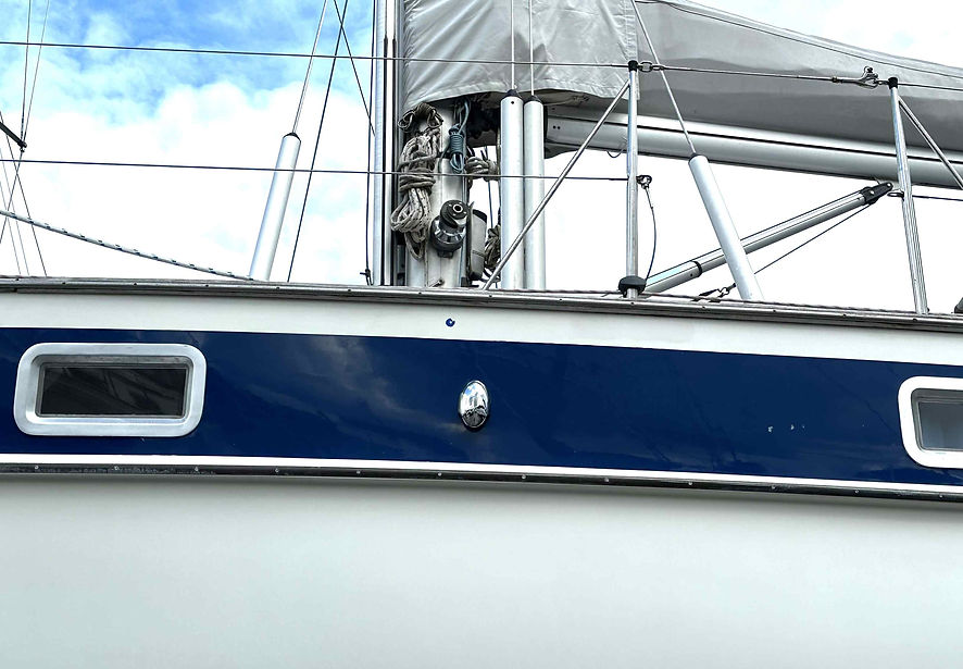
Holding Tank

5mm backing plate (flush with chain plate washers)

Diesel Dipper

Installed in engine bay
